In many homes, you've experienced the simple convenience of flicking a light on or off from two different locations—the top and bottom of a stairwell, perhaps, or both entrances to a long hallway. This seemingly magical feat is accomplished with a pair of 3-way switches. While the installation process might appear daunting at first glance, understanding the right tools, materials, and safety for 3-way switch installation transforms it from a mystery into a manageable project. This guide aims to equip you with the knowledge and confidence to tackle this common home improvement, ensuring a safe, compliant, and ultimately, satisfying outcome.
At a Glance: Your 3-Way Switch Installation Checklist
- Safety First: Always kill power at the breaker and verify with a voltage tester. No exceptions.
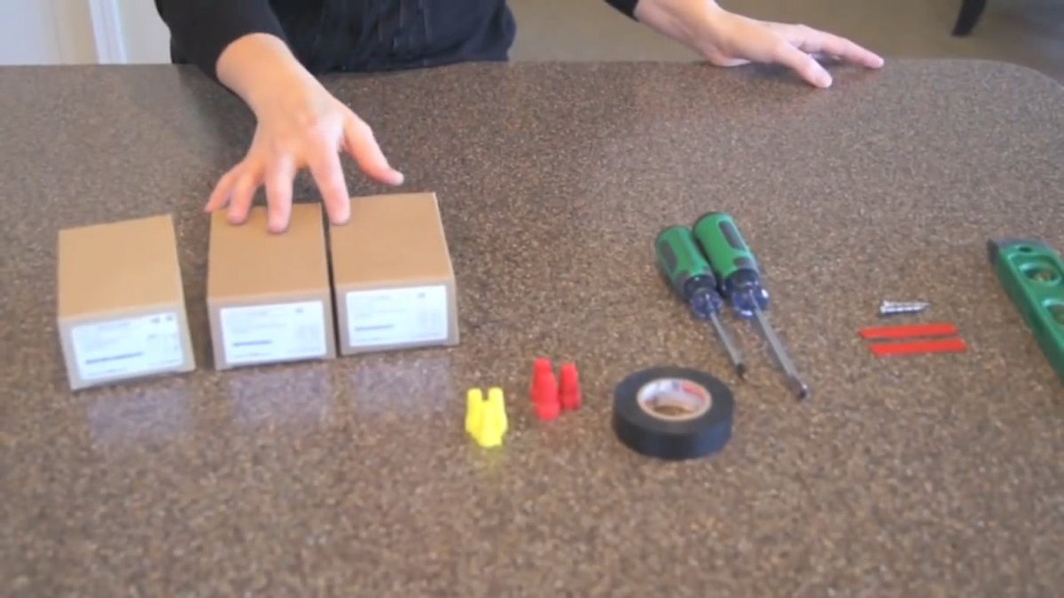
- Essential Tools: Wire strippers, insulated screwdrivers, non-contact voltage tester, utility knife, electrical tape.
- Key Materials: Two 3-way switches, 14/3 or 12/3 NM sheathed cable, wire nuts.
- Identify Terminals: Learn common, traveler, and ground. The common terminal is often darker.
- Two Main Wiring Methods: Power into the first switch box or power into the light fixture box. Correct identification is crucial.
- White Wire Re-identification: Essential for "switch loop" configurations where power enters the light fixture box.
- Test Thoroughly: Confirm the light operates independently from both switches before closing up the boxes.
- Consult Codes: Always adhere to local building codes and the National Electrical Code (NEC). When in doubt, call a pro.
The Convenience Factor: Why 3-Way Switches Are a Game Changer
Imagine walking into a dark room from one door, flipping a switch, and then realizing you need to exit through another door on the opposite side. Without a 3-way switch setup, you’d be walking back to turn off the light, or leaving it on. This is where the simple brilliance of 3-way switching shines. It allows a single electrical load—most commonly a light fixture—to be controlled by two separate switches. The "3-way" label can be a bit misleading; it refers to the three operational terminals (excluding ground) on each switch, not three levels of power or three control points. It's about flexibility and safety, eliminating fumbling in the dark.
Setting the Scene: Non-Negotiable Safety Protocols
Before you even think about picking up a screwdriver, let's talk about the absolute most important aspect of any electrical work: safety. Skimping here is not an option. Electricity is unforgiving, and a momentary lapse can have serious consequences.
Your Golden Rule: Power Down, Always
The very first step—and one you should verbally repeat to yourself every time—is to shut off power at the main service panel. This isn't just about flipping a wall switch; it means identifying the correct circuit breaker for the area you'll be working in and turning it to the "OFF" position.
- Labeling is Your Friend: If your breaker panel isn't clearly labeled, now's the time to fix that. Spend an hour with someone else, systematically testing and labeling each breaker.
- Double-Check: After you've flipped the breaker, try turning on the light fixture or device you're working on. If it stays off, that's a good sign.
- Tape It Off: For extra assurance, place a piece of electrical tape over the "OFF" breaker to prevent accidental re-energization by someone else.
Trust, But Verify: The Non-Contact Voltage Tester
This inexpensive tool is your absolute best friend when working with electricity. After you've turned off the breaker, use a non-contact voltage tester to confirm no current in any wires within the switch box.
- Test the Tester: First, confirm your voltage tester is working by holding it near a known live outlet or wire. It should light up and/or beep.
- Probe the Wires: Carefully insert the tip of the tester into the switch box and probe each individual wire (black, red, white, bare copper). If it signals power, STOP. Go back to the breaker panel, identify the correct breaker, and turn it off. Do not proceed until the tester indicates no power.
Personal Protective Equipment (PPE): Don't Skip It
Just like wearing a seatbelt, wearing the right PPE is a habit that saves lives.
- Insulating Gloves: Even with the power off, insulated gloves provide an extra layer of protection against residual charge or unforeseen circumstances.
- Safety Goggles: Protect your eyes from stray wire fragments, dust, or an accidental arc flash if power is somehow restored.
- Appropriate Footwear: Wear rubber-soled shoes to provide insulation from the ground.
Respecting the Code: NEC and Local Building Requirements
Electrical work is governed by strict regulations for good reason. The National Electrical Code (NEC) sets the standard for safe electrical installation across the U.S., and local building codes often have additional requirements or interpretations.
- Permits and Inspections: Depending on your location and the scope of the project, you might need a permit from your local building department. This often involves an inspection to ensure the work meets code. While it might seem like a hassle, it's there to protect you and your property.
- Know Your Limits: If you're ever uncertain about any part of the installation, dealing with old, complex, or questionable wiring, or just uncomfortable, consult a licensed electrician. Their expertise is invaluable, and ensuring safety and code compliance is paramount. It’s an investment in your home’s safety and value.
Building Your Toolkit: Essential Instruments for Success
Having the right tools not only makes the job easier but also safer. Each tool serves a specific purpose, designed for precision and protection.
1. Wire Strippers: The Precision Artist
- Purpose: To remove the plastic insulation from electrical wires without nicking or damaging the conductor underneath.
- What to Look For: A multi-tool that includes various gauge slots (10-18 AWG are common), a wire cutter, and sometimes a crimper. Insulated handles are a bonus.
- Pro Tip: Always use the correct gauge slot for your wire (e.g., 14 AWG for 14-gauge wire) to ensure a clean strip. Nicking the copper wire can weaken it and create a fire hazard.
2. Insulated Screwdrivers: Your Safe Connection Point
- Purpose: For tightening and loosening terminal screws on switches and outlets. The insulation protects you if you accidentally touch a live component (though power should always be off!).
- What to Look For: A set including Phillips and flathead screwdrivers in various sizes. The insulation should cover the shaft almost entirely, leaving only the tip exposed.
- Pro Tip: Use the correct size screwdriver for the screw head to avoid stripping it.
3. Non-Contact Voltage Tester: Your Guardian Angel
- Purpose: As discussed, this is your primary tool for confirming power is off.
- What to Look For: One with both visual (LED light) and audible (beeping) indicators.
- Pro Tip: Get into the habit of testing every wire, every time. It takes seconds and could save your life.
4. Utility Knife: For Sheathing and More
- Purpose: To carefully cut and score the outer plastic sheathing of NM (non-metallic) cable without damaging the insulated wires inside.
- What to Look For: A retractable blade for safety, with a comfortable grip.
- Pro Tip: Be extremely careful when using a utility knife around wires. Score just enough to crack the sheathing, then peel it back with your hands. Never cut deeply into the cable where the insulated wires are.
5. Electrical Tape: The Versatile Helper
- Purpose: Primarily for re-identifying wire colors (crucial for switch loops), securing connections, or insulating exposed wire ends.
- What to Look For: High-quality vinyl electrical tape that is UL-listed.
- Pro Tip: When re-identifying a white wire as a hot conductor, wrap it thoroughly with black electrical tape near both ends, making it unmistakable.
Other Useful Tools:
- Needle-Nose Pliers: Great for twisting wires together for pigtails or bending wire ends into hooks for terminal screws.
- Lineman's Pliers: Heavy-duty pliers for cutting thicker wires and twisting multiple wires together.
- Headlamp: Frees up your hands and directs light exactly where you need it, especially in dimly lit boxes.
- Multimeter (Optional but Recommended): For advanced troubleshooting, a multimeter can perform continuity checks, measure voltage, and diagnose complex issues.
Gathering Your Materials: What You'll Be Connecting
With your safety gear donned and tools at the ready, it's time to gather the essential electrical components.
1. The Stars of the Show: Two 3-Way Switches
- Purpose: These are the devices that will control your light fixture from two locations.
- What to Look For: Ensure they are indeed 3-way switches (they'll have more terminals than a standard single-pole switch). They come in various colors and styles to match your decor.
- Identifying Terminals: Each 3-way switch will have four terminals:
- Ground Terminal: A green screw or a bare copper wire extending from the switch. This connects to the bare copper ground wire from your cable.
- Common Terminal: Often a darker-colored screw (black or copper/bronze, sometimes clearly labeled "COMMON"). This is the critical terminal. It receives the power source's hot wire at the first switch, or sends switched power to the light fixture from the second switch.
- Traveler Terminals: Two lighter-colored screws (often brass or bronze). These are interchangeable and facilitate communication (sending current back and forth) between the two 3-way switches. When you flip a switch, its internal mechanism shifts the common terminal's connection between these two traveler terminals.
2. The Lifelines: 14/3 or 12/3 NM Sheathed Cable (Romex)
- Purpose: To carry the electrical current between the switches and the light fixture.
- Understanding the Naming: "NM sheathed cable" is commonly known by the brand name "Romex." The "14/3" or "12/3" refers to:
- 14-gauge or 12-gauge: The thickness of the individual copper conductors. 14-gauge wire is suitable for 15-amp circuits, while 12-gauge is for 20-amp circuits. Always match the wire gauge to your circuit breaker's rating.
- /3: Indicates there are three insulated conductors (black, white, red) plus a bare ground wire inside the sheathing.
- Wire Colors and Roles:
- Black: Typically a hot (live) wire.
- Red: Also typically a hot (live) wire, used here as a traveler.
- White: Typically a neutral wire. However, in specific 3-way switch configurations (like a switch loop), the white wire can be re-identified with black electrical tape to serve as a hot wire.
- Bare Copper: The ground wire, always connected to the ground terminals/bundle.
- Pro Tip: Purchase enough cable to comfortably reach between your switch boxes and to the light fixture, adding a few extra feet for slack and future adjustments. It's better to have a bit too much than too little.
3. Wire Nuts: The Secure Connectors
- Purpose: To securely connect two or more electrical wires together.
- What to Look For: Various sizes are available, designed for different numbers and gauges of wires. The packaging will indicate the wire combinations they can handle.
- Pro Tip: Always use wire nuts appropriate for the wire gauge and number of wires you're joining. Twist the wires together firmly with pliers before screwing on the wire nut for a more secure connection.
Other Useful Materials:
- Electrical Boxes: If you're installing new switches or replacing old, damaged boxes, you'll need single-gang or multi-gang boxes, typically plastic for interior walls. Ensure they are rated for the correct volume of wires you'll be putting inside.
- Faceplates: To cover the switches and provide a finished look.
Decoding the Wires: The 3-Way Switch Diagram
Before diving into the actual wiring, it’s critical to understand the journey electricity takes through a 3-way system. The key distinction from a standard single-pole switch is that the common terminal on one switch receives power, and on the other, it sends power to the load (light). The traveler wires simply carry the live connection between the two switches.
Think of the travelers like two parallel railway tracks between two stations (the switches). The common terminal is the train, and each switch decides which track the train is on. When both switches align to put the train on the same track, the circuit is complete, and the light turns on.
The Heart of the Matter: Mastering 3-Way Wiring Methods
The specific wiring method you'll use depends entirely on where your power source (the incoming hot wire from your electrical panel) enters the circuit. This is the single most frequent installation error, so identifying this correctly is paramount.
Crucial First Step: Identify Your Power Source!
Before you start connecting anything, you need to know where the hot power feed is coming from.
- Incoming Power at First Switch Box: If the 14/2 or 12/2 cable (black/white/ground) from your electrical panel enters directly into the box where your first 3-way switch will be located, you're likely using Method 1.
- Incoming Power at Light Fixture Box: If the 14/2 or 12/2 cable from your electrical panel enters the box where your light fixture will be, you're likely using Method 2.
With power off and wires exposed, use your non-contact voltage tester (or a multimeter if you're comfortable, with the power briefly on and extreme caution) to identify the continuously hot wire from your panel.
Method 1: Power Source Enters the First Switch Box (Switch Leg to Light)
This is a common configuration where the incoming power from the breaker panel feeds directly into the first switch box.
What You'll Need:
- Incoming 14/2 (or 12/2) cable from electrical panel (Hot, Neutral, Ground).
- One 14/3 (or 12/3) cable running between the two 3-way switch boxes (Travelers, Neutral, Ground).
- One 14/2 (or 12/2) cable running from the second 3-way switch box to the light fixture (Switched Hot, Neutral, Ground).
Step-by-Step Connections:
- At the First Switch Box:
- Ground: Connect the bare copper ground wire from the incoming power cable and the 14/3 cable to the ground screw on the first 3-way switch. If applicable, connect to the metal box itself.
- Common: Connect the incoming hot wire (usually black) from the electrical panel's 14/2 cable to the common terminal (the darker screw) of the first 3-way switch.
- Travelers: Connect the black and red insulated wires from the 14/3 cable (which runs to the second switch) to the two traveler terminals (the lighter screws) on the first 3-way switch. It doesn't matter which traveler wire goes to which terminal.
- Neutral: The white neutral wire from the incoming 14/2 cable connects directly to the white neutral wire of the 14/3 cable using a wire nut. This neutral wire effectively passes through the first switch box, continuing to the second switch box and eventually to the light fixture. It does not connect to the switch itself.
- At the Second Switch Box:
- Ground: Connect the bare copper ground wire from the 14/3 cable (from the first switch) and the 14/2 cable (to the light fixture) to the ground screw on the second 3-way switch.
- Travelers: Connect the black and red insulated wires from the 14/3 cable (from the first switch) to the two traveler terminals (the lighter screws) on the second 3-way switch. Again, it doesn't matter which traveler wire goes to which terminal, as long as they correspond to the traveler wires from the first switch.
- Common: Connect the black "switched hot" wire from the 14/2 cable (which runs to the light fixture) to the common terminal (the darker screw) of the second 3-way switch. This is the wire that will carry power to the light fixture.
- Neutral: Connect the white neutral wire from the 14/3 cable (from the first switch) to the white neutral wire of the 14/2 cable (to the light fixture) using a wire nut. This neutral also passes through the second switch box, continuing to the light fixture. It does not connect to the switch itself.
- At the Light Fixture Box:
- Ground: Connect the bare copper ground wire from the 14/2 cable (from the second switch) to the light fixture's ground terminal and any other ground wires in the box.
- Hot: Connect the black "switched hot" wire from the 14/2 cable (from the second switch) to the hot terminal (usually black wire) of the light fixture.
- Neutral: Connect the white neutral wire from the 14/2 cable (from the second switch) to the neutral terminal (usually white wire) of the light fixture.
This setup ensures that power flows from the panel to the common of the first switch, then through the travelers to the second switch, and finally from the common of the second switch to the light fixture. For a visual representation, you might find it helpful to review a 3-way switch wiring schematic tailored for this specific power entry point.
Method 2: Power Source Enters the Light Fixture Box (Switch Loop)
This configuration is common when the power feed from your breaker panel enters the ceiling box where the light fixture is located.
What You'll Need:
- Incoming 14/2 (or 12/2) cable from electrical panel (Hot, Neutral, Ground) at the light fixture box.
- One 14/3 (or 12/3) cable running from the light fixture box to the first 3-way switch box (Power to switch, Travelers, Ground).
- One 14/3 (or 12/3) cable running between the two 3-way switch boxes (Travelers, Neutral, Ground).
- (Note: In this method, the white wire in the cable going from the light box to the first switch will be re-identified as a hot wire.)
Step-by-Step Connections:
- At the Light Fixture Box:
- Ground: Connect all bare copper ground wires (incoming power, to first switch, to light fixture) together with a pigtail to the light fixture's ground terminal.
- Hot for Switch Loop: Connect the incoming hot wire (usually black) from the electrical panel's 14/2 cable to the white wire of the 14/3 cable going to the first switch. Crucially, this white wire MUST be re-identified with black electrical tape at both ends to indicate it's now carrying continuous hot power.
- Switched Hot: Connect the black wire of the 14/3 cable (running to the first switch) to the hot terminal (usually black wire) of the light fixture. This black wire will carry the switched hot power back to the light.
- Neutral: Connect the incoming neutral wire (white) from the electrical panel's 14/2 cable to the neutral terminal (usually white wire) of the light fixture.
- At the First Switch Box:
- Ground: Connect the bare copper ground wire from the 14/3 cable (from the light fixture) and the 14/3 cable (to the second switch) to the ground screw on the first 3-way switch.
- Common: Connect the re-identified white wire (wrapped in black tape) from the 14/3 cable (from the light fixture) to the common terminal (the darker screw) of the first 3-way switch. This is your continuous hot feed for the switches.
- Travelers: Connect the black and red insulated wires from the 14/3 cable (from the light fixture) to the two traveler terminals (the lighter screws) on the first 3-way switch.
- Neutral: The white wire from the 14/3 cable running to the second switch is a neutral wire and should be capped off or bundled with other neutrals if present, but it does not connect to this switch. (It will carry neutral between switches if needed for receptacles, but here it's simply a pass-through).
- At the Second Switch Box:
- Ground: Connect the bare copper ground wire from the 14/3 cable (from the first switch) to the ground screw on the second 3-way switch.
- Travelers: Connect the black and red insulated wires from the 14/3 cable (from the first switch) to the two traveler terminals (the lighter screws) on the second 3-way switch.
- Common: Connect the black wire from the 14/3 cable (from the first switch, which served as a traveler for the first segment) to the common terminal (the darker screw) of the second 3-way switch. This is critical: this black wire is now your switched hot returning to the light.
- Neutral: The white wire in the 14/3 cable (from the first switch) is a neutral wire and should be capped off, as it's not used by the switch itself in this configuration.
This setup can be a bit more complex due to the white wire re-identification, but it's crucial for code compliance and safety. Visualizing this can be tricky, so it's a good idea to refer to a detailed wiring diagram for a 3-way switch with the power entering the light fixture.
Pigtailing: The Right Way to Connect Multiple Wires
Often, you'll have multiple ground wires or neutral wires that need to connect. This is where pigtailing comes in.
- Strip: Strip about ¾ inch of insulation from the ends of all wires you want to connect (e.g., three ground wires).
- Twist: Using needle-nose or lineman's pliers, firmly twist the bare copper ends of these wires together clockwise.
- Add Pigtail: Take a short (6-8 inch) piece of matching wire (e.g., bare copper for ground) and twist one end into the bundle you just created. This short piece is your "pigtail."
- Wire Nut: Screw a properly sized wire nut onto the twisted bundle, ensuring no bare copper is visible below the nut. Give the wires a gentle tug to confirm the connection is secure.
- Connect Pigtail: The pigtail then connects to the switch's terminal (e.g., the ground pigtail to the switch's green ground screw). This method creates strong, reliable connections and ensures all components are properly grounded or share a neutral.
The Grand Finale: Securing, Testing, and Troubleshooting
Once all your wire connections are made, it's time to prepare for the moment of truth.
Organizing Wires and Mounting Switches
Carefully fold and organize the wires within the electrical box. You want them to be neat and not overly crowded. Gently push the switches into the junction boxes, aligning the mounting screws with the screw holes in the box. Secure them firmly, but don't overtighten. Finally, install the faceplates.
Restoring Power: The Moment of Truth
Head back to your main service panel and carefully flip the circuit breaker back to the "ON" position.
The Ultimate Test: Flawless Operation
Return to your switches and begin testing.
- Toggle the first switch. The light should turn on or off.
- Go to the second switch. Toggle it. The light should also turn on or off, regardless of the position of the first switch.
- Repeat this several times, ensuring that you can always control the light from either location independently.
If the light consistently turns on and off from both locations, congratulations! You've successfully installed your 3-way switches.
Troubleshooting Common Woes: When Things Go Wrong
Don't panic if your light doesn't work perfectly. Most 3-way switch issues stem from common wiring errors, and they're usually fixable.
- Light Only Works When One Switch is in a Specific Position:
- Diagnosis: This is almost always a misidentified common wire. The common terminal needs to be connected to the continuous hot (from the panel) on one switch, and to the switched hot (to the light fixture) on the other. If one of your traveler wires is connected to a common terminal, you'll get this behavior.
- Solution: Turn off the power immediately! Re-open the boxes. Use your non-contact voltage tester (or multimeter) to re-identify which wire is the continuous hot coming from the panel. This wire must go to the common terminal of the "first" switch (the one receiving power). Similarly, identify the wire that leads directly to the light fixture; this must go to the common terminal of the "second" switch (the one sending power to the load). Ensure the two traveler wires are connected exclusively to the traveler terminals on both switches.
- No Power to the Light At All:
- Diagnosis: This could be a loose connection, a tripped breaker, or a completely incorrect common wire identification.
- Solution: Turn off the power. Check the breaker first. If that's not it, re-check all wire nut connections, ensuring they are tight and that no bare copper is exposed. Double-check that your incoming hot wire is correctly connected to a common terminal and that the wire to the light is connected to the common terminal of the other switch. A multimeter can be invaluable here for continuity checks to ensure power is flowing where it should.
- Light Stays On Continuously:
- Diagnosis: A short circuit or a miswired common connection, possibly connecting hot directly to the light.
- Solution: Turn off the power. This is a more serious issue. Carefully inspect all connections for stray strands or wires touching where they shouldn't. Re-verify the common wire connections and ensure no neutral or ground wires are accidentally connected to a hot terminal.
Beyond the Installation: Best Practices for Longevity & Compliance
Your new 3-way switch setup isn't just about functionality; it's about lasting safety and adherence to standards.
- NEC Adherence: Always strive to meet or exceed NEC guidelines. This includes proper wire and circuit labeling within your panel, using a circuit breaker that matches the load and wire gauge (e.g., 15A breaker for 14-gauge wire, 20A for 12-gauge), and ensuring secure cover plates and mounting for all switch boxes.
- Quality Materials: Investing in high-quality insulated cables, appropriate wire nuts, and reputable brand-name switches and outlets pays dividends in safety and durability. Cheap components are a false economy when it comes to electricity.
- Documentation: It’s a good practice to keep a record of any significant electrical work you perform, noting which circuits control what, wire types used, and the date of installation. This can be invaluable for future troubleshooting or when selling your home.
Remember, while this guide aims to be comprehensive, there's no substitute for hands-on experience or the expertise of a professional. If you encounter anything that makes you uncomfortable, or if the wiring in your home appears significantly different or more complex than described, do not hesitate to call a licensed electrician. Your safety and the safety of your home are always worth it.
Ready to Flip the Switch? A Final Word on Confidence
Installing 3-way switches is one of those DIY projects that feels incredibly rewarding. It demystifies a core part of your home's electrical system and provides a practical upgrade to your living space. By focusing on meticulous safety procedures, understanding your tools and materials, and carefully following the wiring steps, you've gained a valuable skill. Take pride in your work, enjoy the newfound convenience, and now you have a deeper appreciation for the silent, unseen network that powers your home. Go ahead, flip that switch!