Mastering your home's lighting can transform how you live in your space. If you've ever wished you could turn off a light from both ends of a hallway or control your stairwell light from upstairs and downstairs, you're ready for a 3-way switch. This Step-by-Step 3-Way Switch Installation Guide will walk you through the process, empowering you to wire your home safely and efficiently, no matter your experience level.
Forget fumbling in the dark or making extra trips just to hit a light switch. Installing a 3-way switch system adds unparalleled convenience and safety to your home. But let's be clear: working with electricity demands respect and precision. This comprehensive guide combines expert insights with clear, actionable steps, ensuring you understand not just how to connect wires, but why each connection matters.
At a Glance: Your Quick Start Checklist
Before we dive into the nitty-gritty, here’s what you need to know and have ready:
- Safety First: Always de-energize the circuit at the breaker and verify with a voltage tester.
- Tools: Voltage tester, wire strippers, screwdriver set, diagonal cutters, electrical tape, flashlight.
- Materials: Two 3-way switches, appropriate NM-B cables (14/2, 14/3 for 15-amp circuits; 12/2, 12/3 for 20-amp), wire nuts, electrical boxes, faceplates.
- Understanding Basics: Familiarize yourself with common and traveler terminals.
- Code Compliance: Be aware of NEC (National Electrical Code) requirements, especially for neutral wires.
- Patience: Take your time, double-check every connection.
Why Two Switches Are Better Than One: Understanding 3-Way Control
Think about a standard light switch. It's a simple on/off mechanism, controlling power to a light from a single point. That's a "single-pole" switch. But what if you have a long room, a staircase, or a garage with two entrances? Constantly walking back to one switch to turn lights off gets old fast.
Enter the 3-way switch system. This clever setup allows you to control the same light (or group of lights) from two different locations. It's not magic; it's smart electrical engineering. For even more control points—say, three or four locations—you'd integrate 4-way switches, but we'll focus on the fundamental two-location setup for now.
What a 3-Way Switch Actually Does
Unlike its single-pole cousin, a 3-way switch isn't just opening or closing a circuit. It's a Single Pole Double Throw (SPDT) device. Imagine it as a tiny railway switch, redirecting the "train" (current) down one of two tracks.
Each 3-way switch has three distinct terminals:
- The Common Terminal: This is the anchor point. On one switch, it receives the incoming hot power. On the other, it sends the switched hot power out to the light fixture. It's typically a darker color (black or bronze) and physically set apart from the others, making it easy to identify.
- The Traveler Terminals: These are the two "tracks" for the current. Usually brass-colored, they're where your "traveler wires" connect. When you flip the switch, the common terminal's connection toggles between these two traveler terminals, changing the path of electricity without ever completely breaking the circuit.
The Vital Role of Traveler Wires
The traveler wires are the communication link between your two 3-way switches. They carry power back and forth, enabling either switch to complete the circuit and turn the lights on or off.
You'll typically find these two wires—one red, one black—bundled together within a single 3-wire cable (like 14/3 or 12/3 NM-B). The order in which you connect the red and black traveler wires to their respective brass traveler terminals on either switch doesn't matter. What does matter is that they only connect to traveler terminals, never to a common terminal. Connecting a traveler to a common by mistake is a surefire way to prevent your system from working, or worse, to create a short circuit.
Before You Begin: The Absolute Essentials (Safety First!)
Before you even think about picking up a screwdriver, prioritizing safety is non-negotiable. Electricity is powerful and unforgiving.
Shut Down the Power & Double-Check
This is the golden rule: Always de-energize the circuit at your main electrical panel by flipping the appropriate breaker to the "off" position. Don't just rely on an existing wall switch; those only control the load, not the incoming power.
Once the breaker is off, verify that the power is indeed gone. Use a non-contact voltage tester or a multimeter. Touch the tester to the wires you'll be working with. No beep, no light? Good. Still, proceed with caution and treat all wires as if they're live until you're absolutely certain. This practice, known as Lockout/Tagout (LOTO) in professional settings, prevents accidental re-energization.
Essential Tools & Materials for Success
Having the right tools makes all the difference for a safe and efficient installation:
- Non-Contact Voltage Tester or Multimeter: Absolutely critical for verifying power is off.
- Wire Strippers: For safely removing insulation without damaging the conductor.
- Screwdriver Set: Phillips and flathead, insulated handles are a plus.
- Diagonal Cutters: For cutting wires.
- Electrical Tape: For insulating connections and re-identifying wires.
- Needle-Nose Pliers: Handy for shaping wires into hooks for terminals.
- Flashlight or Headlamp: To illuminate dimly lit electrical boxes.
Materials Checklist: - Two 3-Way Switches: Ensure they are rated for your circuit's amperage.
- NM-B Cable:
- 14/2 NM-B (for 15-amp circuits): Contains black (hot), white (neutral), bare copper (ground).
- 14/3 NM-B (for 15-amp circuits): Contains black, red (travelers), white (neutral), bare copper (ground).
- Use 12/2 and 12/3 NM-B for 20-amp circuits. Always match cable gauge to circuit breaker amperage.
- Wire Nuts: Various sizes for securing splices.
- Electrical Boxes: Properly sized for your wires and switches (check box fill calculations).
- Faceplates: To cover the switches once installed.
Understanding Cable Types and Amp Ratings
Choosing the correct wire gauge is vital for safety and to comply with electrical codes.
- 15-Amp Lighting Circuits: These are the most common for residential lighting. You'll need:
- 14-2 NM-B cable: For the power supply coming into the first switch, and for the connection from the second switch to the light fixture.
- 14-3 NM-B cable: For the run between the two 3-way switches. This cable includes the two traveler wires (typically red and black) plus a neutral and ground.
- 20-Amp Lighting Circuits: If your lighting circuit is protected by a 20-amp breaker, you must use heavier gauge wire to prevent overheating:
- 12-2 NM-B cable: For power in and light out.
- 12-3 NM-B cable: For between the switches.
NEC Compliance: What You Need to Know
Adhering to the National Electrical Code (NEC) is non-negotiable. It’s not just about passing inspection; it’s about preventing fires and electrical hazards.
- Grounded Enclosures (NEC 404.9): All switches must be installed in grounded electrical boxes. If you're using metal boxes, they must be properly bonded (connected to the ground wire). Plastic boxes are inherently non-conductive, but switches inside them still need their ground screw connected to the circuit's ground wire.
- Neutral Wire Requirement (NEC 404.2(C) - 2011 cycle): This is a critical modern code update. Most new switch boxes are required to have a grounded (neutral) conductor present, even if the traditional mechanical switch doesn't directly use it. This accommodates future smart switches, dimmers, or other electronic devices that often require a neutral connection for power. This means older "dead-end" switch loop methods (where only hot and switched hot wires enter the box, and no neutral) are no longer compliant for new construction. Our guide follows the compliant "power-in-switch" method.
- Re-identification: If you use a white wire as a hot conductor (e.g., as a traveler, though not in the method described here), it must be re-identified with black, red, or other colored electrical tape at both ends to indicate it's no longer a neutral. (NEC 200.7(C)).
Your Step-by-Step 3-Way Switch Installation Guide (Power-in-Switch Method)
This guide assumes the most common configuration: the "power-in-switch" method, where the incoming hot power feed enters the first switch box.
Step 1: Shut Down the Power & Double-Check
We can't stress this enough. Go to your electrical panel, locate the breaker controlling the circuit you'll be working on, and flip it OFF. Use your non-contact voltage tester or multimeter to confirm absolutely no power is present in the wires you'll be handling. This is your first and most critical safety step.
Step 2: Map Your Cable Runs
Successful 3-way wiring starts with correctly routed cables. This isn't just about pulling wire; it's about establishing the electrical pathways.
- From Panel to First Switch: Run a 2-wire cable (e.g., 14/2 NM-B for 15-amp) from your electrical panel (your power source) to the first switch box. This cable brings in the continuous hot power and a neutral.
- Between Switches: Run a 3-wire cable (e.g., 14/3 NM-B for 15-amp) from the first switch box to the second switch box. This cable will carry your two traveler wires, plus a neutral and ground.
- From Second Switch to Light: Run another 2-wire cable (e.g., 14/2 NM-B) from the second switch box to the light fixture box. This cable will carry the switched hot to the light and a neutral.
Ensure all cables are properly secured within the walls, using staples where necessary, and leave enough length inside the boxes (typically 6-8 inches) for easy manipulation and connection.
Step 3: Prepare Your Wires for Connection
With cables run, it’s time to prepare the conductors.
- Cut Sheathing: Carefully cut away the outer sheathing of each cable within the electrical boxes, exposing the insulated conductors. Be mindful not to nick the insulation of the inner wires.
- Strip Insulation: Using your wire strippers, remove about 3/4-inch of insulation from the end of each individual conductor (black, red, white).
- Grounding Pigtails: Cut several 6-inch lengths of bare copper wire. These will be used as "pigtails" to ensure proper grounding of the switches and boxes.
Step 4: Wiring the First 3-Way Switch (Power Source Side)
This switch receives the incoming power. Remember your common and traveler terminals.
- Ground Wires: Gather all bare copper ground wires from both the incoming 2-wire power cable and the 3-wire cable going to the second switch. Twist them together with a 6-inch bare copper pigtail using a wire nut. Connect the free end of the pigtail to the green ground screw on your 3-way switch. If you have a metal box, also connect a separate pigtail from this ground bundle to the ground screw on the box.
- Neutral Wires: Take the white neutral wire from the incoming 2-wire power cable and the white neutral wire from the 3-wire cable going to the second switch. Splice them together with a wire nut. Do NOT connect these neutral wires to the 3-way switch itself. They simply pass through this box.
- Common Wire: Locate the black (hot) wire from the 2-wire power source cable. This is your continuous hot feed. Connect this black wire to the black or bronze "common" screw terminal on the 3-way switch.
- Traveler Wires: Take the red and black wires from the 3-wire cable (these are your travelers). Connect one to each of the two brass-colored traveler terminals on the switch. The specific terminal for red or black does not matter, as long as they are connected to the traveler screws.
- Insulate & Secure: Once all connections are made and secure, wrap electrical tape around the body of the switch to cover the exposed screw terminals. This provides an extra layer of insulation. Carefully fold the wires into the box, ensuring they aren't pinched, and screw the switch into the box.
Step 5: Wiring the Second 3-Way Switch (Light Fixture Side)
This switch sends power to the light fixture.
- Ground Wires: Similar to the first switch, gather all bare copper ground wires—from the 3-wire cable coming from the first switch and the 2-wire cable going to the light fixture. Twist them together with a 6-inch bare copper pigtail using a wire nut. Connect this pigtail to the green ground screw on the 3-way switch and to the metal box (if applicable).
- Neutral Wires: Splice the white neutral wire from the 3-wire cable and the white neutral wire from the 2-wire cable (going to the light) together with a wire nut. Again, do NOT connect these neutral wires to the switch. They pass through to the light.
- Common Wire: Locate the black wire from the 2-wire cable that runs to the light fixture. This is the "switch leg" (the switched hot that will power the light). Connect this black wire to the black or bronze "common" screw terminal on the second 3-way switch.
- Traveler Wires: Take the red and black traveler wires from the 3-wire cable that came from the first switch. Connect one to each of the two brass-colored traveler terminals on this switch. As before, the order of red/black doesn't matter for the traveler terminals.
- Insulate & Secure: Wrap electrical tape around the switch body, then carefully fold the wires and screw the switch into its box.
Step 6: Connecting Your Light Fixture
The final step in the wiring sequence is at the light fixture itself.
- Ground Wire: Connect the bare copper ground wire from the 2-wire cable to the green ground screw on the light fixture (or the fixture's mounting strap).
- Neutral Wire: Splice the white neutral wire from the 2-wire cable to the white neutral wire or terminal on the light fixture.
- Switched Hot Wire: Splice the black "switch leg" wire from the 2-wire cable to the black hot wire or terminal on the light fixture.
- Mount Fixture: Carefully attach the light fixture to the electrical box, ensuring no wires are pinched.
Step 7: The Final Countdown: Securing & Testing
You're almost there! It's time to bring your new 3-way system to life.
- Secure Switches: Once the wiring is complete in both switch boxes, carefully push the switches into their respective boxes and secure them with the provided screws.
- Install Faceplates: Attach the decorative faceplates over the switches.
- Re-energize: Go back to your electrical panel and flip the circuit breaker back to the "ON" position.
- Test Thoroughly: Go to each switch location and test the lights. Flip the first switch on, then off. Then go to the second switch, flip it on, then off. Ensure that you can turn the light on and off from either location, regardless of the position of the other switch. Try all possible combinations.
If everything works as expected, congratulations! You've successfully installed a 3-way switch system.
Beyond the Basics: Advanced 3-Way Scenarios
While the "power-in-switch" method is standard, it's good to understand other configurations and enhancements. For a deeper dive into the exact electrical pathways, you might find it helpful to review a detailed how to wire a 3-way switch diagram.
Understanding "Dead-End" Loops (Re-identification)
In older wiring, you might encounter a "dead-end" switch loop where the power enters the light fixture box first, then a 2-wire cable runs down to a switch box, and then back up to the light. In this scenario, a white wire within that 2-wire cable often carries the hot current down to the switch.
According to NEC 200.7(C), if a white wire is used as an ungrounded (hot) conductor, it must be re-identified at both ends with black, red, or other colored electrical tape to indicate it's not a neutral. While this was common, new construction generally avoids dead-end loops in favor of methods that bring a neutral to the switch box, as required by modern code.
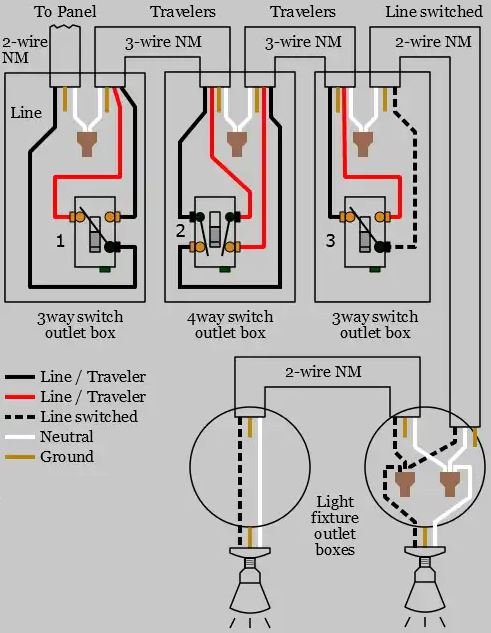
Adding More Control Points: When to Use 4-Way Switches
What if two control points aren't enough? For control from three, four, or even more locations, you'll need to introduce 4-way switches. A 4-way switch is essentially a "crossover" switch.
It's always installed between two 3-way switches. The traveler pair from the first 3-way switch connects to one pair of terminals on the 4-way switch, and the traveler pair going to the second 3-way switch connects to the other pair. You can daisy-chain multiple 4-way switches in the middle of a circuit to add as many control points as you need.
Stepping into Smart Home Control: Smart 3-Way Switches
Modern homes increasingly integrate smart technology. If you're looking to upgrade to smart 3-way dimmers or switches, the neutral wire requirement becomes particularly relevant. Most smart switches need a constant power source to operate their internal electronics, and they get this power from the neutral wire.
Smart 3-way kits often come as a "master" and "remote" (or "companion") switch pair. The master switch usually handles the actual load switching and communication, while the remote simply sends signals to the master. Always follow the manufacturer's specific wiring diagrams for smart switches, as they can differ significantly from traditional mechanical switches, and incorrect wiring can damage the components.
Troubleshooting Common 3-Way Switch Hiccups
Even experienced DIYers can encounter issues. Here's how to diagnose and fix the most common problems:
System Not Working At All?
- No Power: Did you remember to flip the breaker back on? Is the breaker tripped?
- Loose Connection: A wire nut might be loose, or a terminal screw not tightened enough. Go back and check every single connection point in both switch boxes and the light fixture.
- Miswired Common: The most frequent culprit. The line hot (from the panel) or the switch leg (to the light) has been connected to a traveler terminal instead of the common terminal on one of the switches. Re-identify and re-connect.
- Ground Fault/Short: Are any bare wires touching a metal box or another wire? This will trip the breaker.
- Bad Switch: While rare, a switch could be faulty out of the box.
Lights Only Work From One Switch?
This usually points to a problem with the traveler wires or their connection to the traveler terminals.
- Traveler Wires Reversed/Loose: Ensure both traveler wires are securely connected to the traveler terminals on both switches, not the common.
- Open Traveler: One of the traveler wires might be broken or disconnected somewhere along its run, or a wire nut connecting them is loose (less common in the power-in-switch method as travelers are usually direct).
Flickering Lights or Breaker Tripping?
- Loose Connections: This is a big one for flickering. Any loose wire can cause intermittent contact.
- Overloaded Circuit: Is the total wattage of your lights (and any other devices on that circuit) exceeding the circuit's capacity?
- Short Circuit: A hot wire touching a neutral or ground wire, or a metallic enclosure, will immediately trip the breaker. This requires careful inspection for damaged insulation or pinched wires.
Professional Practices for a Smooth Installation
- Clear Identification: Use colored electrical tape to mark any re-identified wires.
- Secure Connections: Don't just twist wires; use proper wire nuts that hold firmly. For screw terminals, wrap the wire clockwise around the screw and tighten until snug, but don't overtighten to avoid stripping.
- Box Fill Calculations: Before you close up your boxes, ensure you haven't crammed too many wires and devices into them. NEC Article 314.16 dictates box fill limits to prevent overheating and maintain safety. Overcrowding can lead to fire hazards.
- Thorough Testing: Don't just test "on" and "off." Test all permutations from both switch locations.
Remember, troubleshooting often requires a logical, step-by-step approach. Start at the power source and work your way through the circuit with your multimeter to trace voltage.
When to Call a Pro: Knowing Your Limits
While this Step-by-Step 3-Way Switch Installation Guide aims to be as comprehensive and empowering as possible, there are times when it’s simply safer and smarter to call a licensed electrician.
- Uncertainty: If at any point you feel unsure, confused, or uncomfortable with a step, stop. Your safety is paramount.
- Old or Damaged Wiring: If you discover old, brittle, or damaged wiring in your walls, it’s best left to a professional to assess and update.
- Overcrowded Boxes: If your electrical boxes are already packed, or you're unsure about box fill calculations, a pro can ensure code compliance.
- Repeated Breaker Trips: If you're constantly tripping breakers, it indicates a deeper electrical issue that needs expert diagnosis.
- Permit Requirements: Some local jurisdictions require permits for electrical work. An electrician can guide you through this process.
There's no shame in knowing when to defer to an expert. A small investment in professional help can prevent costly mistakes, potential hazards, and give you peace of mind.
Your Home, Mastered: A Final Word on Safe Wiring
Successfully installing a 3-way switch system is incredibly rewarding. It not only enhances the functionality and convenience of your home but also provides a deeper understanding of its electrical backbone. By following this guide, prioritizing safety, and adhering to code, you've taken a significant step toward mastering your home's electrical needs.
Keep in mind that while this guide is extensive, it serves as a general framework. Always consult the latest edition of the NFPA 70, National Electrical Code (NEC), and any specific state and local electrical codes applicable to your area for definitive compliance. Stay curious, stay safe, and enjoy the newfound control over your lighting!